Software
Blender 3.0
Adobe Photoshop 2022
Unity
Vuforia
Quixel Bridge
Quixel Megascans
1.1 Concept
In year two my philosophy was to engage with as many different assignments as reasonably possible. The reasoning was primarily diversity but also to see if I can tackle various projects simultaneously yet deliver completed high quality work on multiple fronts.
1.2 Project Aim
Building The Earth Museum (TEM) content for application in a schools learning virtual environment by providing models that are interlinked across the globe.
1.2.1 Image sourced from: (Berkeley.edu, 2022)
1.3 The Client - The Earth Museum
The Earth Museum is an experimental not-for-profit enterprise, with a vision to create a virtual learning resource used in every home, classroom, museum and place, sharing and connecting the world’s cultural and natural heritage with people and places; empowering us to understand each other and look after the planet better.
1.4 Future Implication & Target Audience
Soon after completion all 3d models will be linked to The Earth Museum's 2d explorer map and at a later date all models will be incorporated into the earth museum's 3d explorer map. This project however may also serve as catalyst for museums on their journey towards digitalization.
1.5 Target Audience
Primari Audience
Key Stage 3 (12-14 years old school children)
Key Stage 4 (12-14 years old school children)
Secondary Audience
Dr Janet Owen
Museum Stakeholders
1.6 The Team & Roles
Our group consisted of four 3d students of various pathways from the Digital Media Development Department:
My main responsibility as elected team leader was to liaise between the client and the team. I also made sure the team adhered to all deadlines.
1.7 Deliverables
All members were free to select from four sets of models representing exhibition items of four subsequent museums partners of TEM. Individual choices were as follows:
The two models I selected were intentional choices for quite different reasons. I picked Thrust 2 because I fell in love with the rich motoring history behind the making of this extraordianry car. The client Janet offered two alternatives. I could model either the car itself or the scale model (1.7.1) made by Brian Ball one of the originial Thrust 2 team members. (1.7.2) Although the scale model is quite remarkable on its own, I unequivocally came to the decision to replicate the original car. (1.7.3) My experience through past projects proved I work more efficiently if I find a connection with my subject. It is My passion for speed and anything fast warranted the choice.
1.7.3
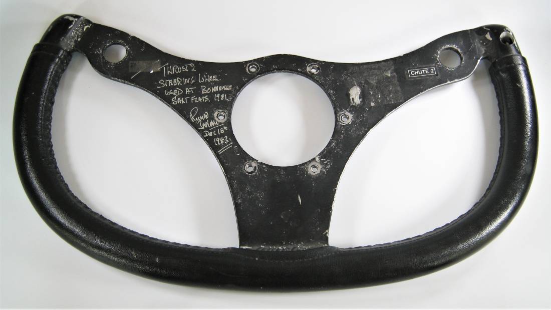
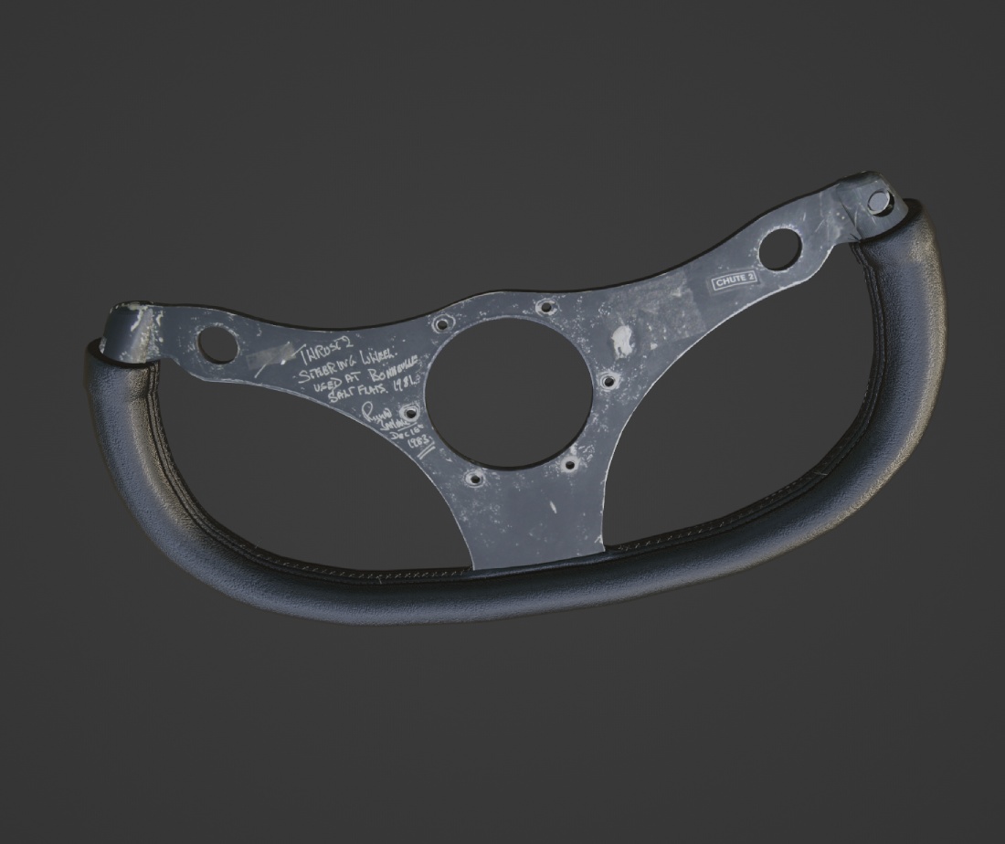
The second candidate the steering wheel of Thrust 2 (1.7.4) also came from the collection of The Isle of Wight Heritage Centre. This instance however my choosing was guided by my resolve towards realism itself. I was rather keen to capture the moment with a simple yet life like scene.
1.7.4
1.8 Formatting Requirements
All models had to adhere to the following requisites:
Suplementary animation videos to be included:
A supporting handover document to be also supplied.
1.9 Client Research
I have been familiar with the work of the Earth Museum as I have met Dr Janet Owen at various networking events. Even so I gained more project specific insights when I attended two events directly relating to the Explorer Quest Application whithin which our models will be used eventually. The Explorer Quest is a web based somewhat gamified 3d feature TEM will implement into their website in the future delivering a more relateable platform for KS3 and 4 students. First I participated in the prototype testing of the app in November 2021 then more recently during a design challenge in April 2022. In both occassions I took part proactively providing feedback and suggestions for improvements. These experiences proved to be excellent opportunities to understand where the fututre of education is heading using cutting-edge technology such as virtual and augmented reality, additionally facilitating in conception of how 3d assets are utilized within a scholastic environment.
2.0 Moodboards
Creating moodboards is a key element of my design process. The benefits cannot be overstated. It builds a general cross-reference point that can be used throughout all project phases. It also sets the mood (hence the name) and varrants cohesion. Out of the hundreds of researched photos I made separate moodboards for different aspects of my subjects. Taking advantage of the great features of an app called PureRef I collated and selected the most relevant visual evidence and categorised them into groups refering to their respective use. One particular feature of the application is that all images can be added to a large moodboard organised into various categories. (2.0.1) The groups I classified and their corresponding roles are as follows: 1. Land speed record history - to gain a general understanidng of the importance of the original project carried. 2. Thrust 2 - it is a basic step before modelling anything to gather as much visual references as possible for establishing the general and detailed design particulars of the model accurately. 3. The steering wheel - same principles apply as for the car, materials and textures - a crucial step towards producing realistic work. 4. Location - this goes hand in hand with the textures and materials but also assists in generating the scene atmosphere in a life-like fashion. 5. Physics and effects - thise are rather purposive when reproducing effects such as the jet engine flames, dust clouds created by the car or the visibly built up pressure waves as described by Richard Noble.
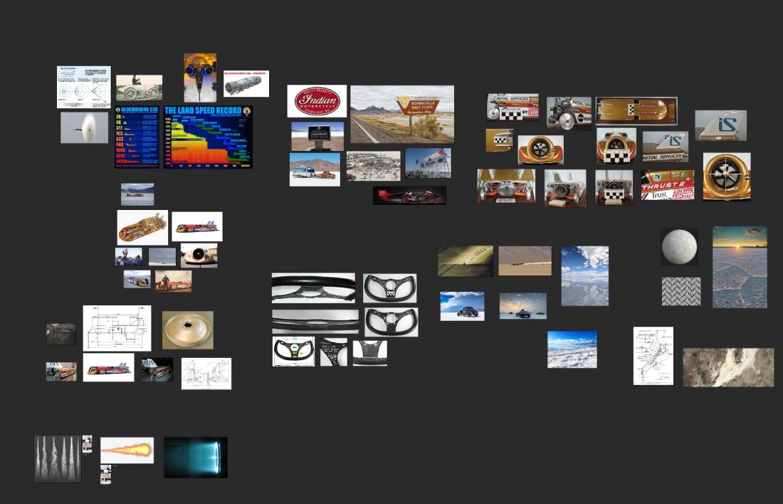
2.0.1
2.1 The Steering Wheel
I made a separate section for the design process for both models as I treated them as somewhat separate parts or projects throughout. The following segments will solely refer to the whole creation of the steering wheel while the Thrust 2 equivalent will start at section 3.0.
2.2 Research & Design
Opposed to the lack of available photographs of Thrust 2 I was in luck owing to the abundance of accurate images of the steering wheel. My moodboard consisted of photos from various angles and measurements. (2.2.1)
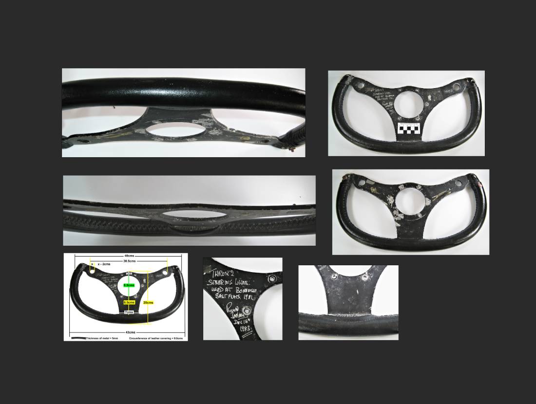
2.2.1
2.3 Modelling the Steering Wheel
One unique point I had to pay particular attention before modelling was the fact of lens distortion. (2.3.1) Due to the angle and the distance between the object and camera when the photo was taken plus also accounting for lens curvature some image distortion is expected. To counter this I modelled only the left side of the centre of the wheel and applied a mirror modifier. This also helped in reducing the number of vertices.
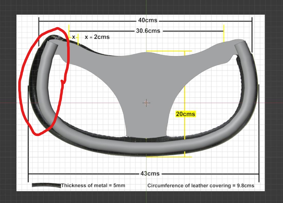
2.3.1
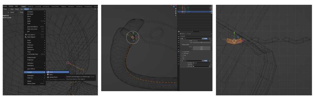
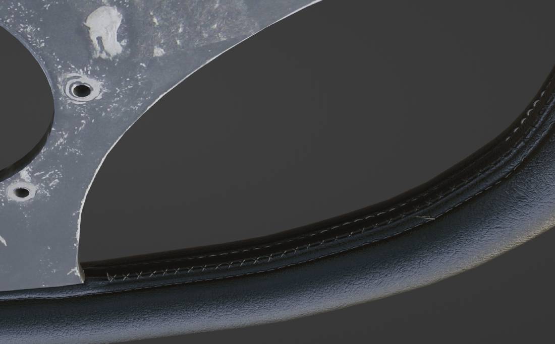
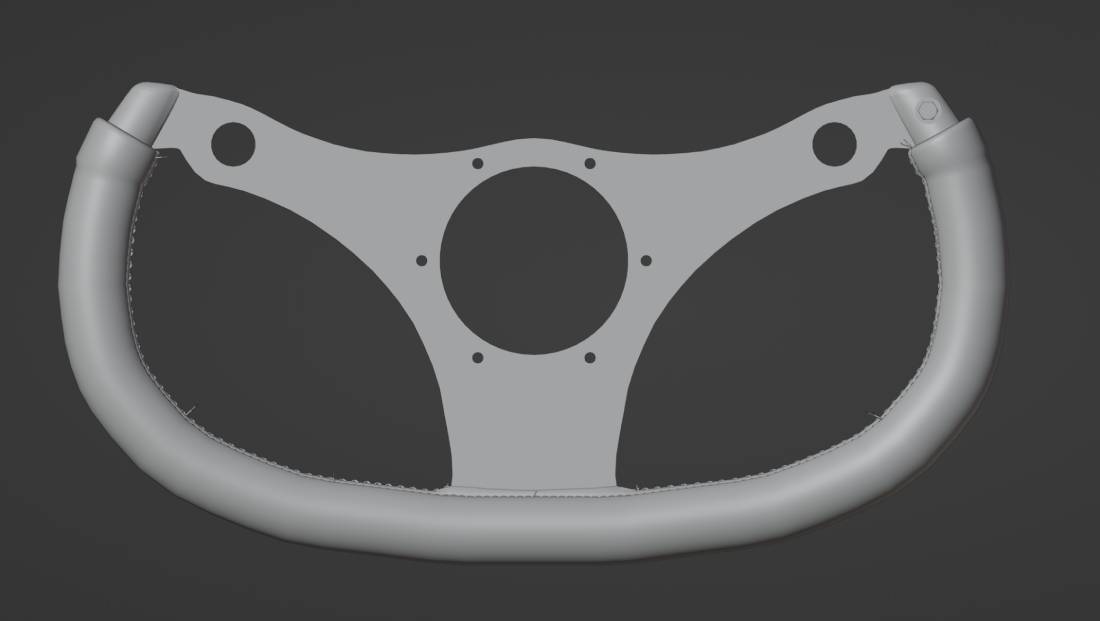
The modelling process was relatively simple. The main steps: First I added a reference image as an empty. Then I made a bezier curve following the centre of the steering wheel grip curvature. Once this was done I converted the cure into mesh and added thickness to it. (2.3.2) Normally I tend to trace the outline of the to be modelled object images by exturding and moving vertices of models and smooth the edges. This time however I reverted to different techniques. To model the centre of the wheel I made a bezier curve tracing the edges similarly to the reference picture and made a mould like 3d object that I used to carve the shape out of an added plain by using the intersect (knife) tool from the face menu. As an experiment the same technique was called upon to make the holes. (2.3.3) I find this a more accurate method in comparison with the boolian modifier that can add inconsistent topology. To accurately position the holes sorrounding the centre hole the following steps were taken: 1.added an empty, 2. added and positioned a cylinder, 3. added an array and curve modifier to the cylinder, 4. the curve followed the empty, 4. since six holes were needed by dividing the angle of a full circle by the number of holes I rotated the empty by 60 degrees finishing the phase. Next I extuded the faces of the cut out centre plain to gain thickness. In order to have a realistic tear/cut in the leather grip I selected edges where the bottom centre of the middle meets the grip. Then from the Edge Context Menu the Edge split tool was used. To finish this step I moved the separated edges into appropriate position. (2.3.4) Finally I added seems for better UV mapping results. (2.3.5)
2.4 The Bolt
There is a bolt within the hole on the top right side of the steering wheel. I used a free Blender Add-on called Bolt Factory to add a bolt and the nut. The add-on makes these objects highly custumisable yet there is one downside. The bolts especially the threds composed by an excessive amount of verts. Given the constraint by the stated maximum number of triangles within the brief I simply deleted the invisible topology saving thousands of verts in the process. This was particularly beneficial since one of the following phases the making of leather stiches required a considerable amount of vertices an I was already near the maximum limit.
In order to achieve an overall realistic look for the entirity of the model details need to be immaculate. The attached image demonstrates the node network used to produce the needed life like steel bolt texture. (2.4.1) The following steps were implemented:
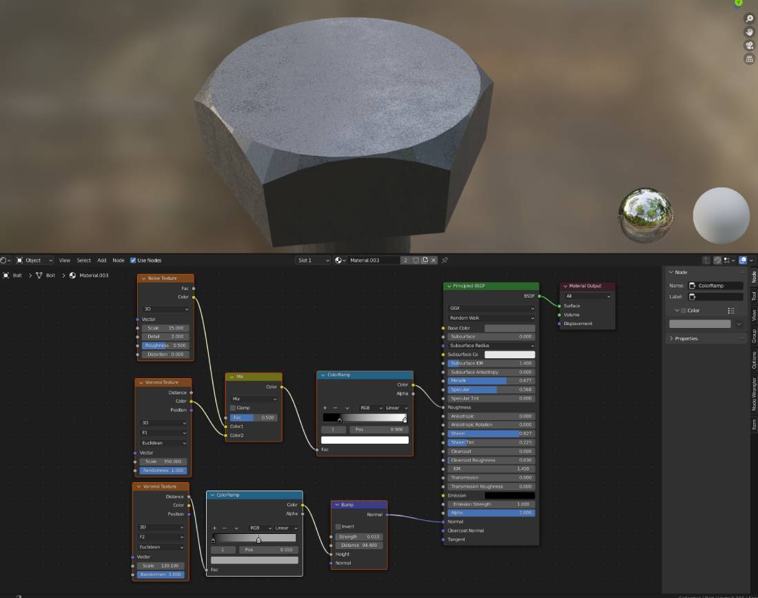
2.4.1
2.5 Leather Texture
During the project I mainly used procedural materials instead of image textures apart from the front inside of the steering wheel. Image textures can be large in size therefore a more efficient way to recreate materials such as leather is to utilize Blenders built in node network. The full node network grouped by functions for clarity purposes. (2.5.3) Details of the finished material can be observed on the last image. (2.5.4) With the intention of generating a genuine leather look I proceeded as per the following:
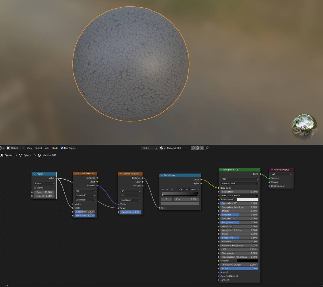
2.5.1
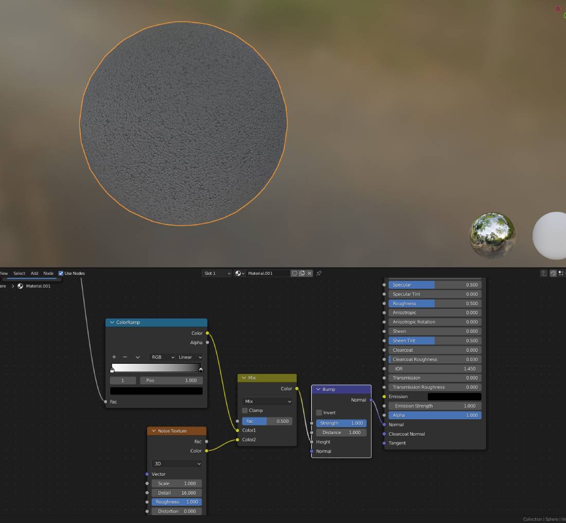
2.5.2
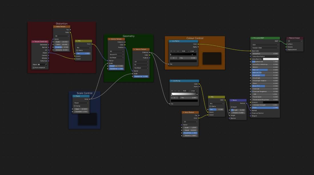
2.5.3
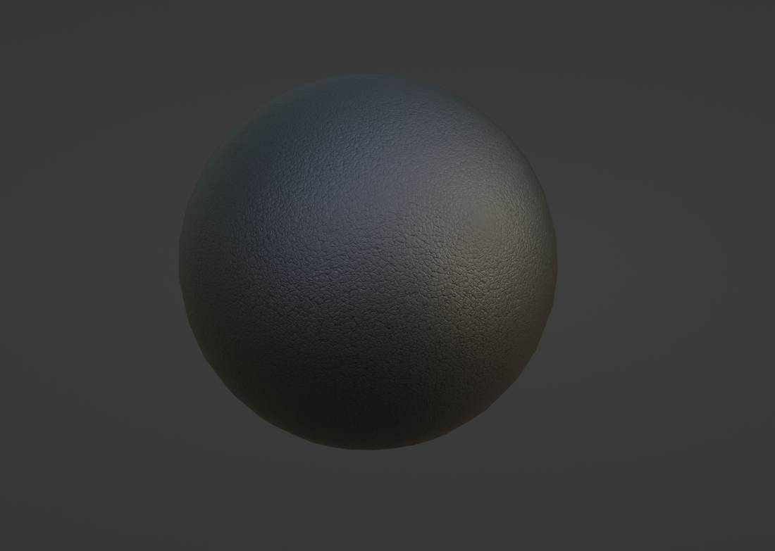
2.5.4
2.6 Digital Stitching
A prominent feature of the steering wheel is the stitching on the leather. After some experimentation the recreation was a rather simple process. The main steps taken are: (2.6.1)
2.6.1
2.7 Attention to Detail
By browsing through countless images of renders by renowned artist I perceived some important steps that can make or brake the illusion of 3d realism. Attention to detail is key here. Braking patterns and symetry just a start. Variety and added detail is also invaluable. I unstraightened the curves what the stitching follows by moving vertices. The individual stitches also made up of 5 variants contributing to unorderly pattern. (2.7.1) I added some scaled down, grouped, twisted and bent cylinders representing sticking out thred ends. (2.7.2)
2.7.1
2.7.2
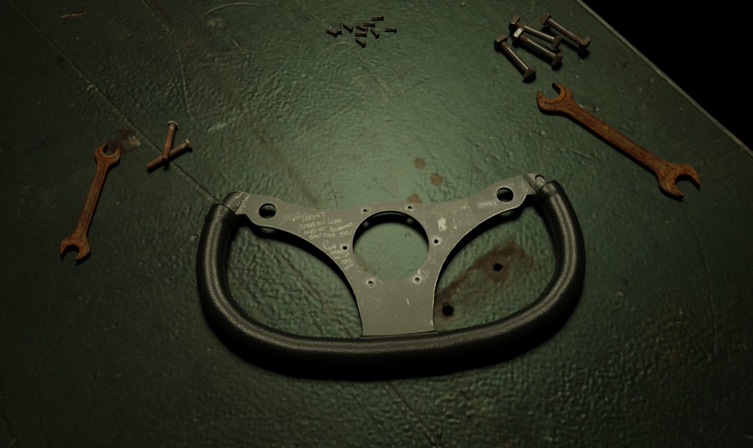
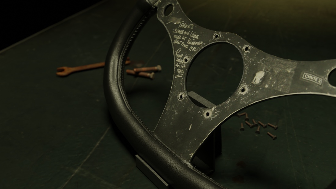
2.8 Building a Mini Scene
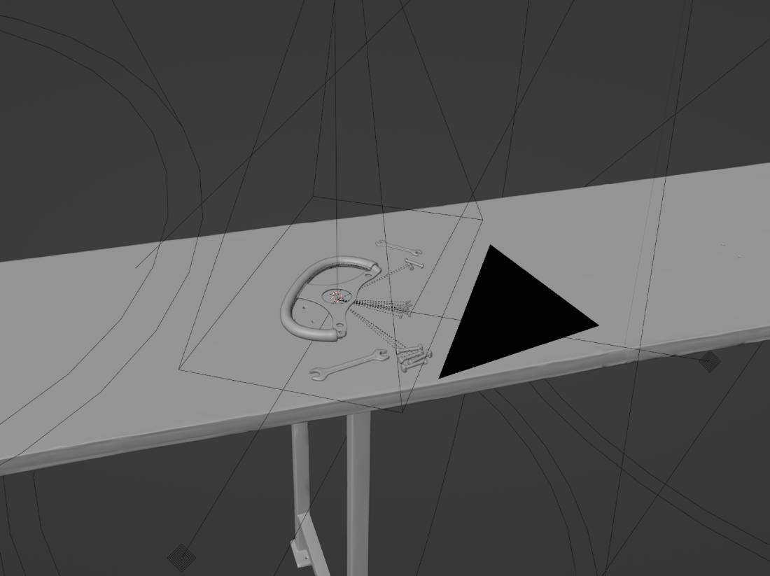
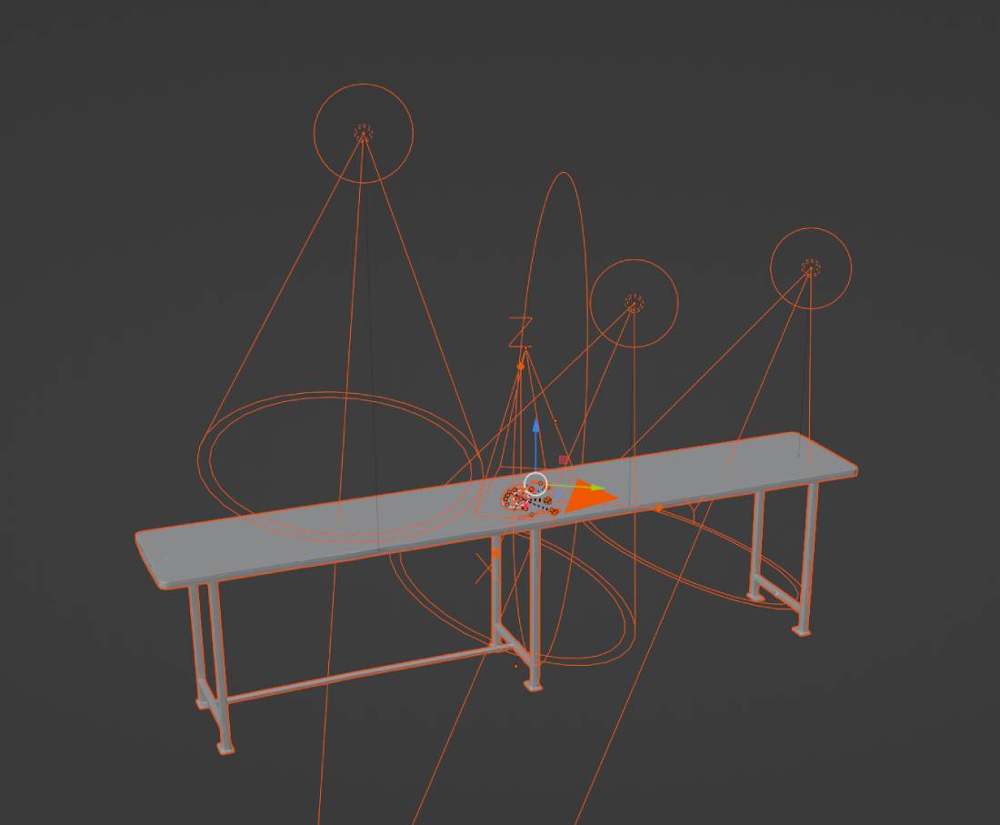
Although it was not a client requirement I created a small scale scene for added realism and the purpose of exhibiting my work in an atmospheric environment. I imported some assets such as a workbench, bolts and wrenches, through Quixel Bridge from Quixel's Megascans library. The scene was populated after the textures of the imported models were fixed. (2.8.1) For some reason when importing from Megascans into Blender some of the texture nodes came plugged into incorrect slots. Once these were remedied a few spotlights were added for a warehouse / garage like atmosphere. (2.8.2) I rendered out a few images in Blender's built-in Cycles engine testing different perspectives by changing the camera angles and focal length. The focus point was changed and the f-stop lowered for adding depth of field. Unfortunately I forgot to save for about two hours straight. Normally this is a natural process every few minutes this time however I made a mistake and failed to remember. For an unknown reason Blender crashed and I was not able to recover the last session.
2.8.1
2.8.2
2.9 Conclusion 1
Making the steering wheel was probably the most enjoyable modell I made up to date. The echoing mistake of failed saving is a perfect reminder not to repeat the same error. Excluding this however the project transpired without any issues. I discovered how drastically small details can transform a scene. By producing multiple materials I gained an in depth knowledge of Blenders node network. An added bonus as a result of displaying the final renderes at the Transmedia 2022 exhibition and the kind action of Lucy Hopkins and Alex Prichett may have an oportunity to freelance to a Hampshire based game studio.
3.0 Thrust 2 The Land Speed Record Braking Car
3.0.1
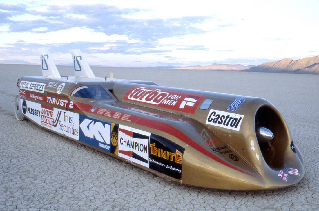
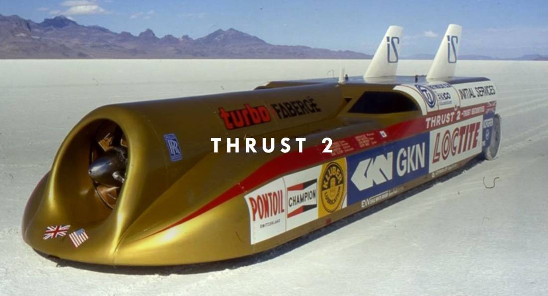
"Wanted - 650 mph Car Designer" said the advertisement in the September 1977 issue of "Cars and Car Conversions". Behind those words was the Scottish entrepreneur Richard Noble. One of the many applicants was John Ackroyd a British visionary engineer/designer. Somewhere on the Isle of Wight in a small workshop a 30000 horsepower jet engine fastened to a steel frame on four cast alloy wheels formed the base of the plan that was supposed to change motoring history. Forward six years in the alkali flats of Black Rock Desert a dream became reality and a new world record was set. Thrust 2 driven by Noble achieved 633.468 mph (1019.468 km/h). (3.0.1, 3.0.2)
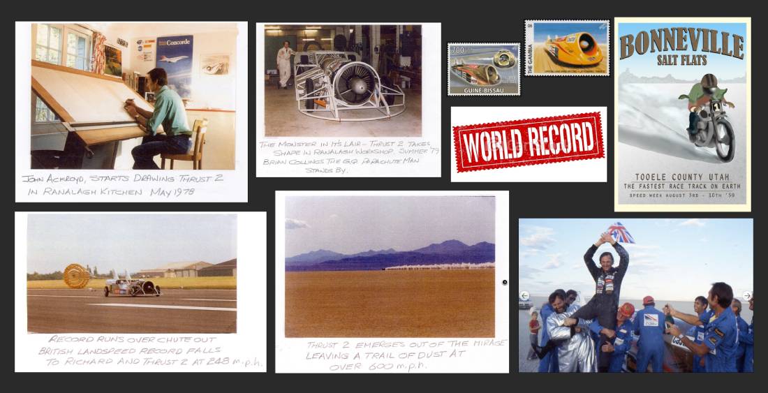
3.0.2 Image source: (Hudson, 2022)
3.1 Land Speed Record
The land speed record (or absolute land speed record) is the highest speed achieved by a person using a vehicle on land according to Wikipedia. Mankind fascination with speed dotted through history. With the invention of motorized wehicles this passion has reached new hights. From the very first speeding ticket issued to the currently held record set by the Thrust SSC standin at 1227.986 Km/h the goal has always been the same: Go faster. (3.1.1)
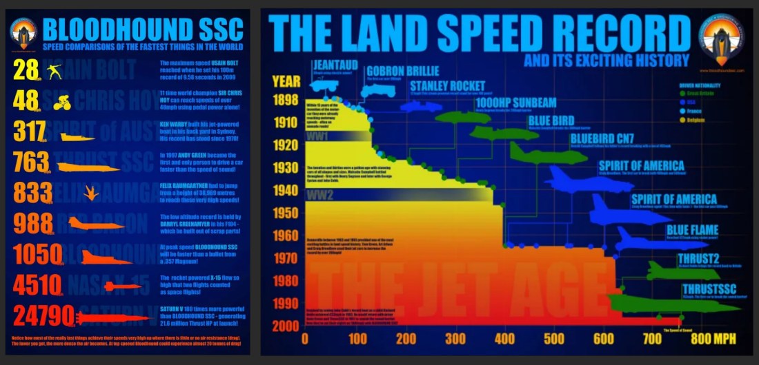
3.1.1 Image source: (Bloodhound Education, 2019)
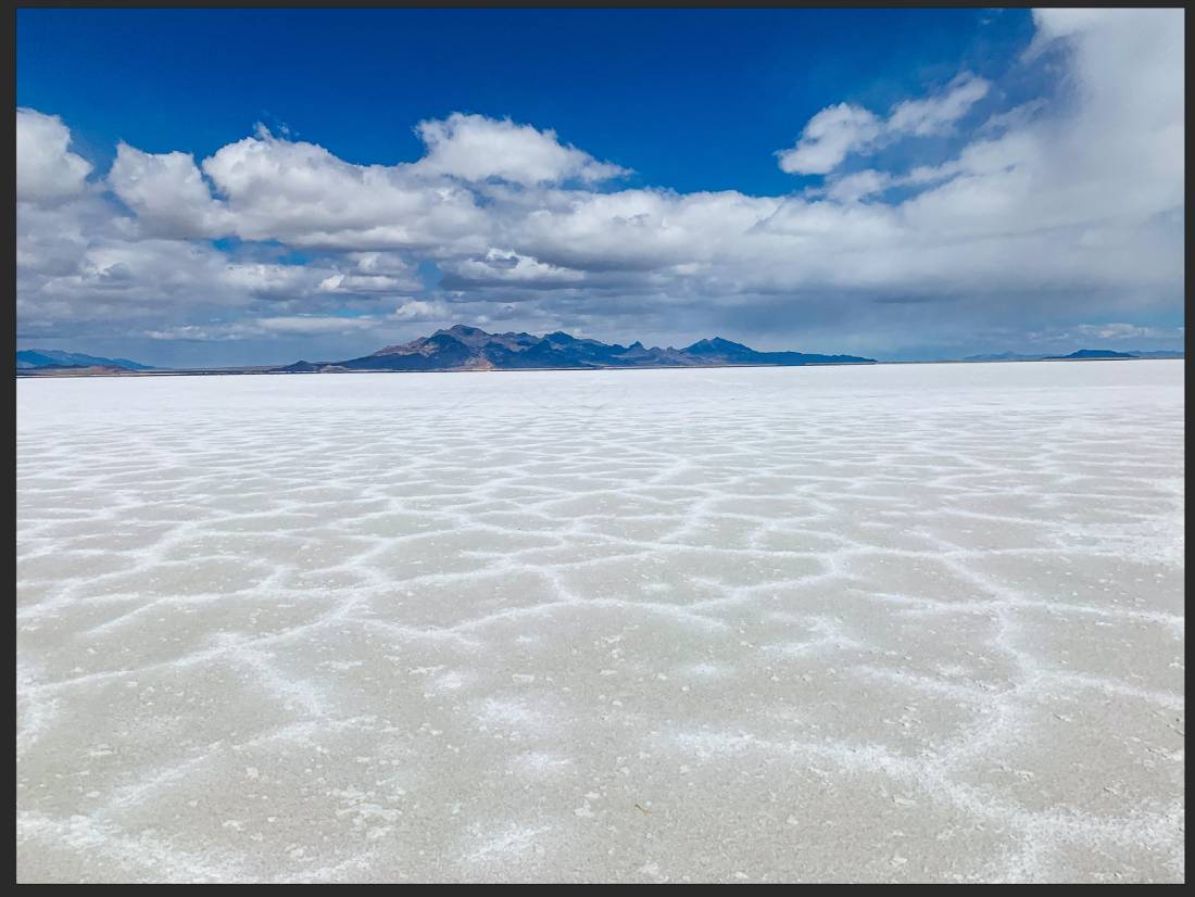
3.2 Welcome to Boneville Speed Week
Although many records were set on public roads, with the evolution of automotive technology especially the application of supersonic jet engines enthusiast developed the need for more suitable environments. Salt flats or dried-up lakebeds represented the ideal location with miles and mils of straight evenly surfaced areas. Boneville Utah, USA is such particular locations where Speedweek is held every year. (3.2.1) Throughout this six day event high speed adrenalin junkies from all over the word come to Boneville to race.
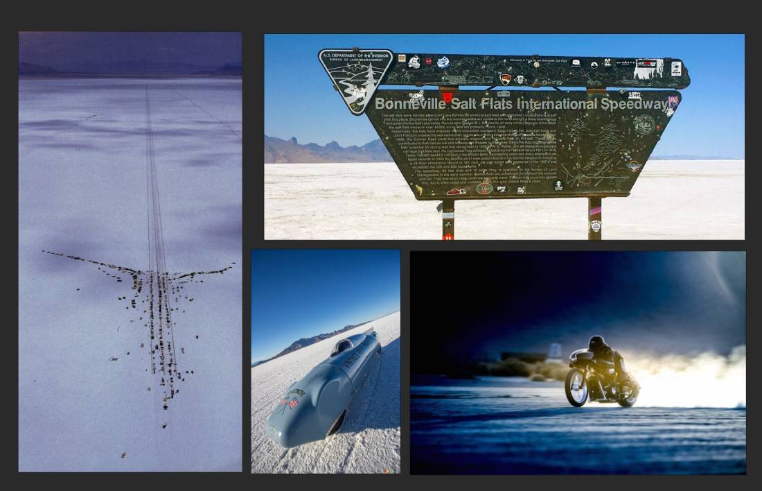
3.2.1 Image source: (Performance Racing Industry, 2020)
3.3 Referencing Thrust 2
I wanted to recreate a scale replica of the car however due to the lack of available data and the simple fact that Blender is rather a visual representation tool than a precision engineering software like Auto CAD I applied my artistic freedom. (3.3.1) Although efforts were made to stay true to the original car as much as possible in many instances I could only rely on partial images or none at all for references therefore I improvised. I employed an add-on called MeasureIt to precisely measure dimensions. (3.3.2)
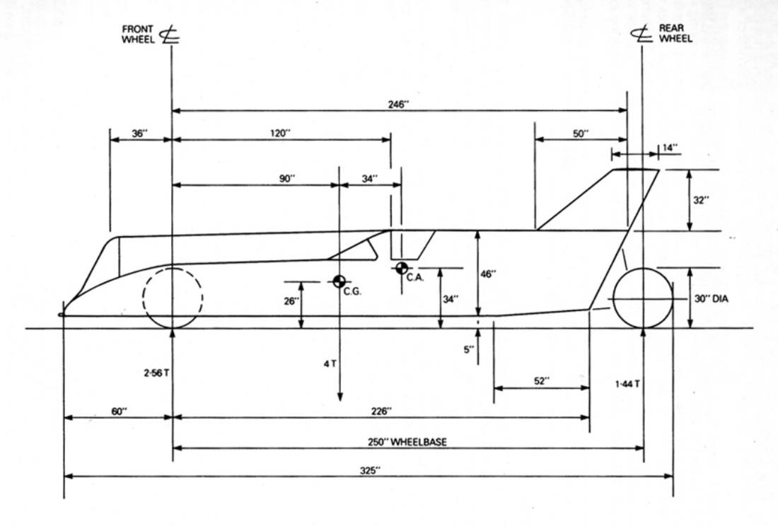
3.3.1 Image source: (Hudson, 2022)
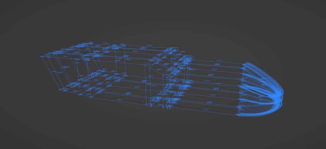
3.3.2
3.4 Modelling Thrust 2
The base outline of the bodywork may look simple but the front end especially involves bevellings and scaling from various angles. It took a few iteration to achiver the desired final shape. (3.4.1) Distorted reference images made the modelling task challenging at times. (3.4.2) Creating realism through detail resulted in taking a lot of precious time. Topology issues riddled this phase often needing to reverting to remodelling parts from zero.
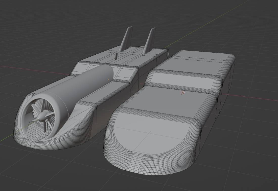
3.4.1
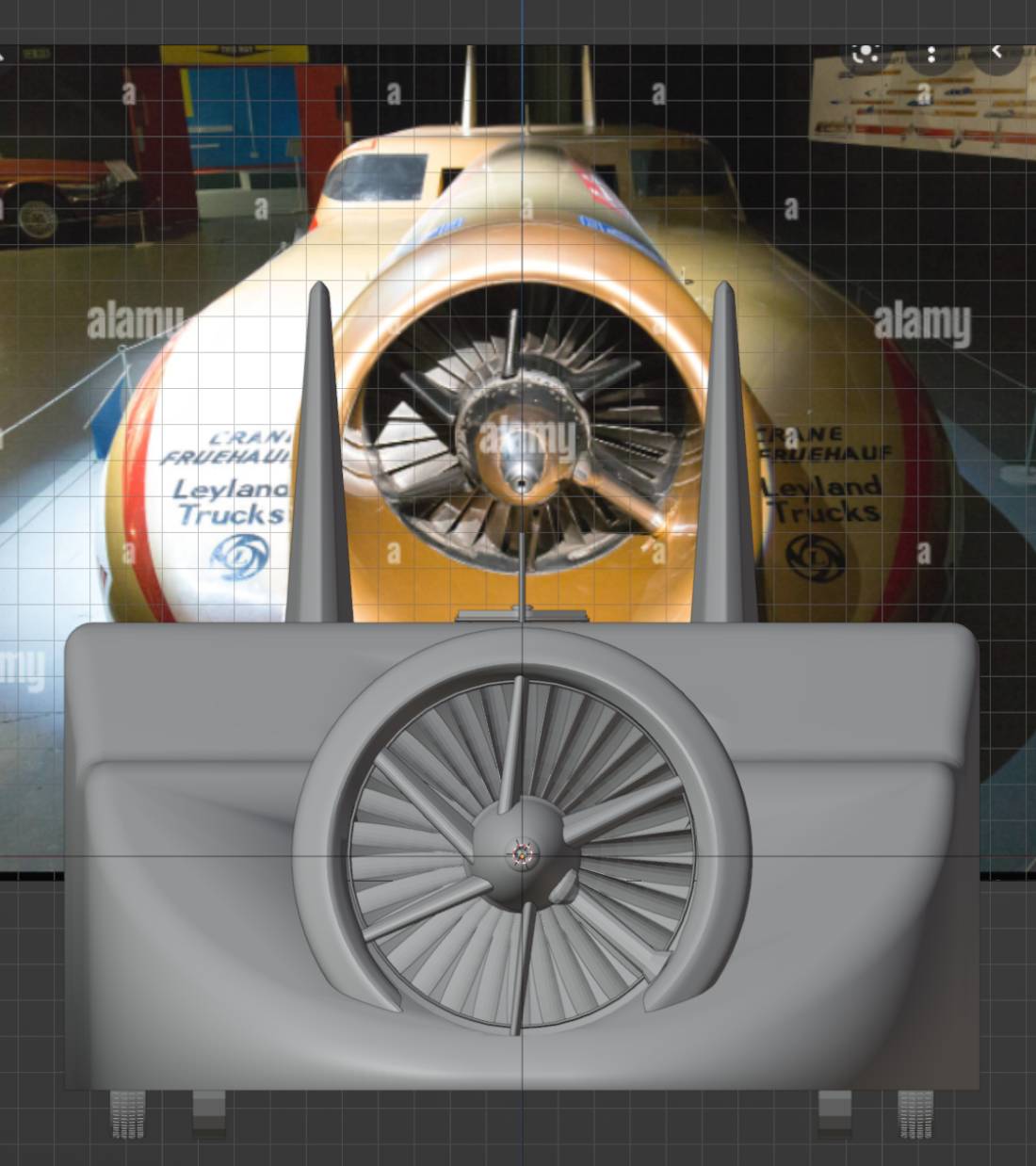
3.4.2
The limiting number of triangles consequently calld for some intuitive techniques. One particular occassion was the recreation pf the parachute cable. As a modelling exercise I wanted to recreate the texture of the woven material through modelling. To achieve this the following steps were taken: (3.4.3, 3.4.4)
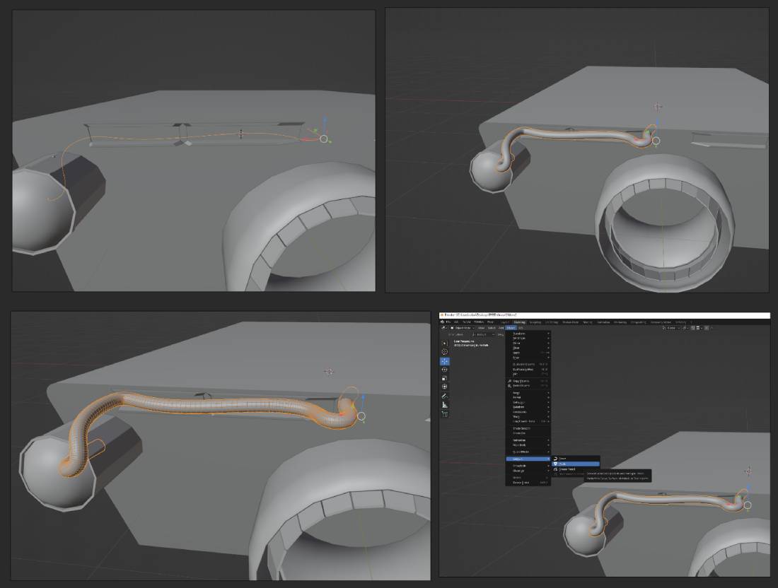
3.4.3
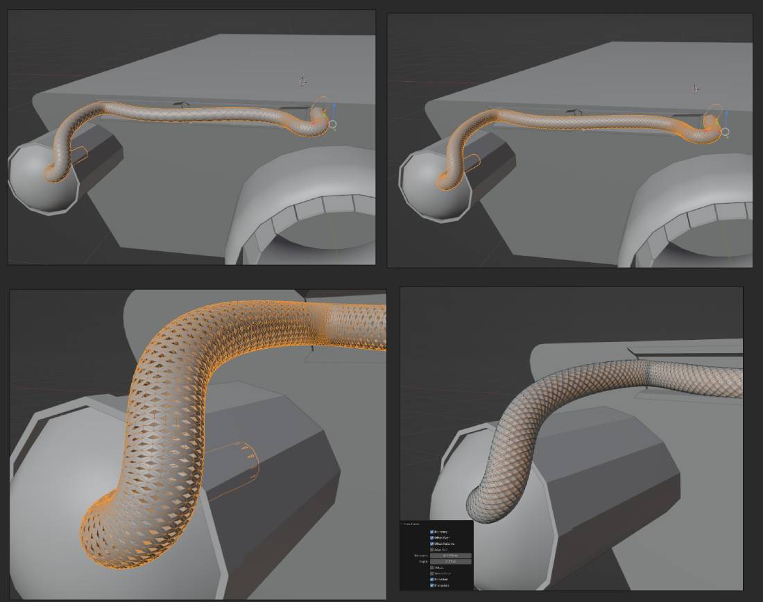
3.4.4
Modelling the more populated rear end with the wheels and shock absorbers required much adjustment in terms of repetitive scaling, moving and repositioning.
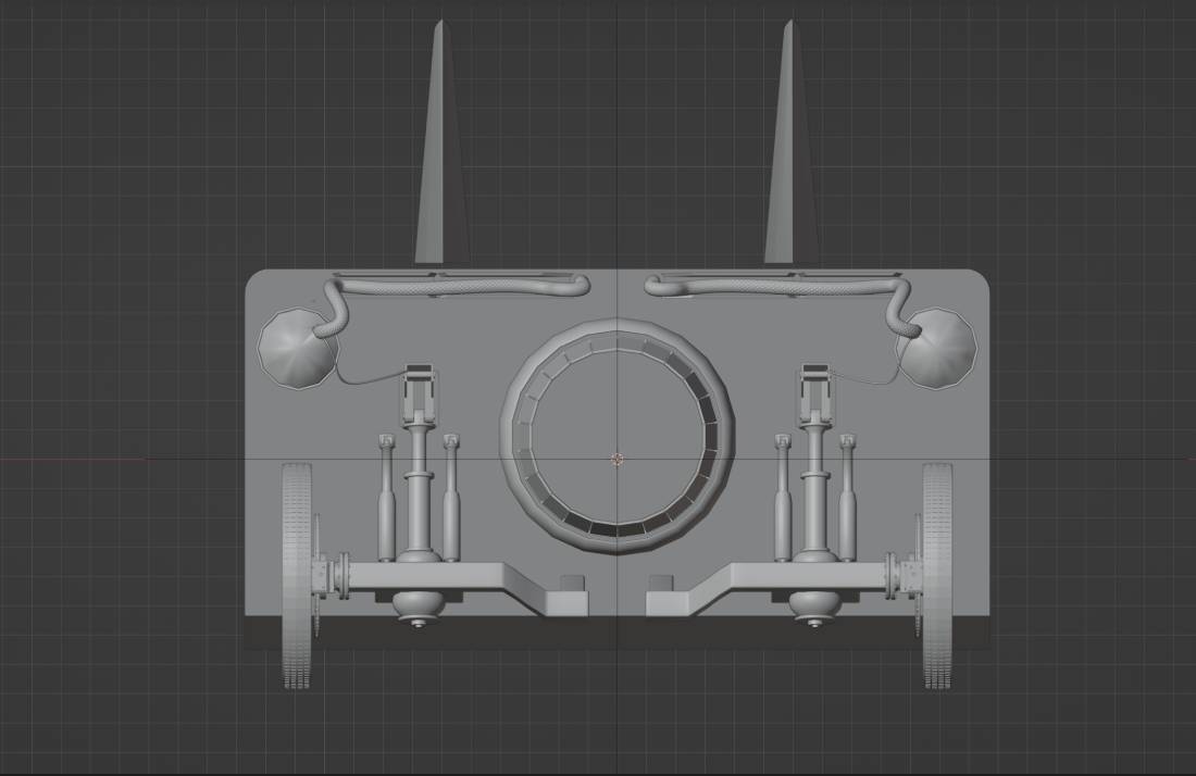
3.4.5
3.5 Texturing and Materials
Texturing started with UV mapping groups of faces and applying and experimenting with numerous mainly metallic materials such as brushed aluminium, chrome, brass, scratched painted metal etc. (3.5.1)
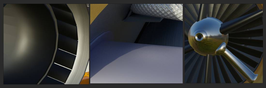
3.5.1
Without any reliable information regarding to the base colour of Thrust 2 I utilized a Google Chrome extension called Eye Dropper. With this tool I was able to sample any colour from pictures online. One variable that I did not expect was since the paint is metallic lights from different sources and agles cast different shades. I sampled almost a dozen colours but finally settled with HEX#bb9960. In order to achieve the metallic particles and shine I used a simple node network. (3.5.2)
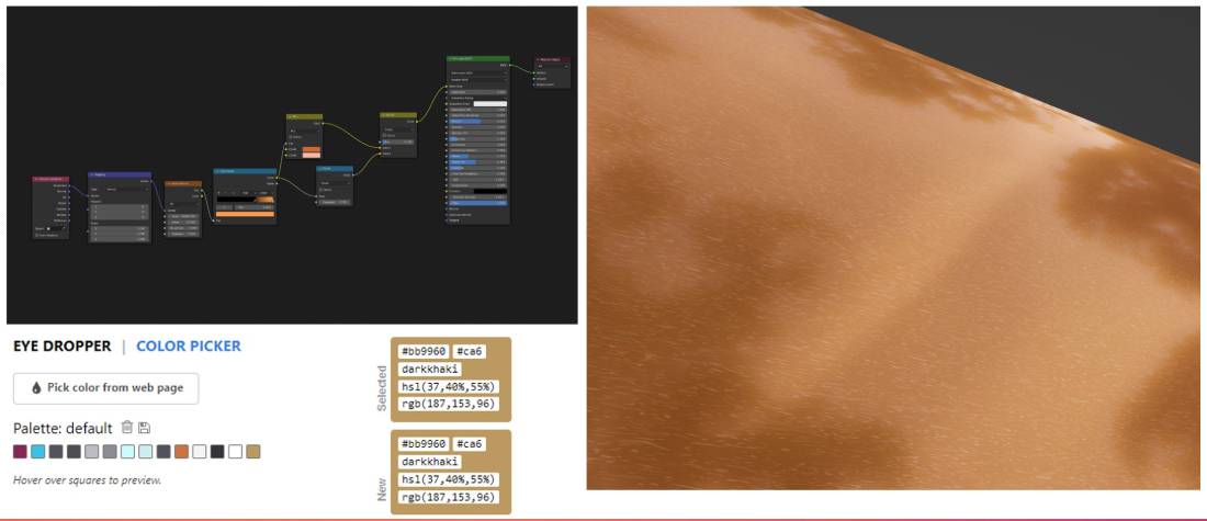
3.5.2
3.6 Unfinished Scene
Although 98% of client requirement has been fulfilled on time I was not able to complete the texturing - namely the stickers on the bodywork. This however have been discussed with the client and will be supplied in the upcoming days. Other aspects such as a separate scene I worked on could not be finished due to circumstances described under the time management section. My plan was to make an alkali lake bed environment similar to Boneville. I really wanted to recreate the white salt chrystal formations on the ground. (3.6.1) I spent many days experimenting on various terrain types. (3.6.2) Finally I asked my lecturer Rob's help. With his guidance I would have been able to replicate the environment but I was running out of time and the added pressure of additional assignments, presentations, exhibition prevented completion. Additionally I made some props such as traffic cones and distance marker flags. And downloaded a brush for making track markings on the salt (3.6.3) The plan was to animate the car with jet flames and kicked up dustcloud and have a luodspeaker voiceover completing a full Virtual Reality scene.
3.6.1
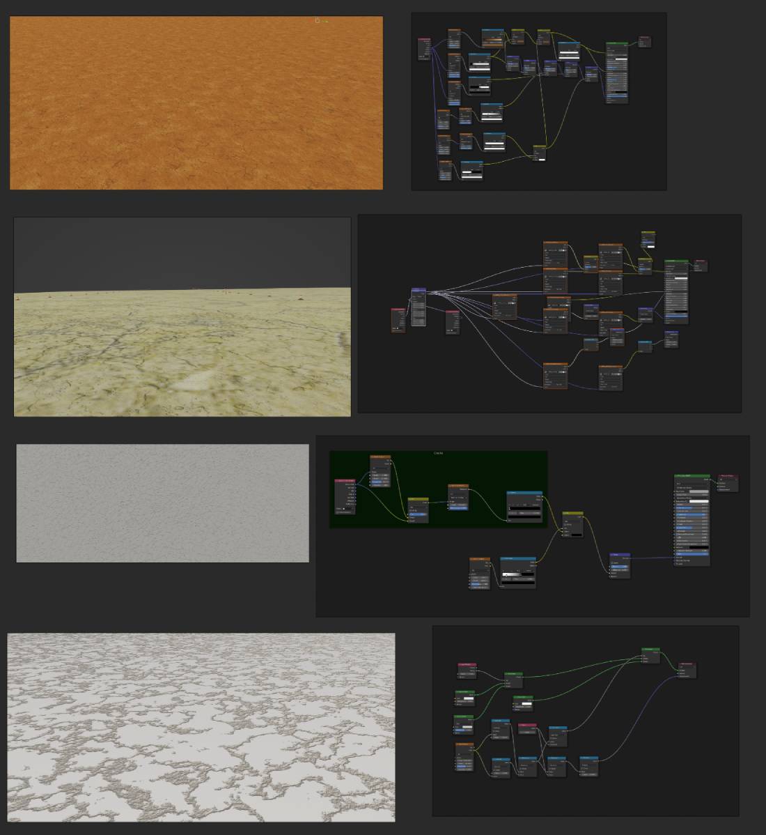
3.6.2
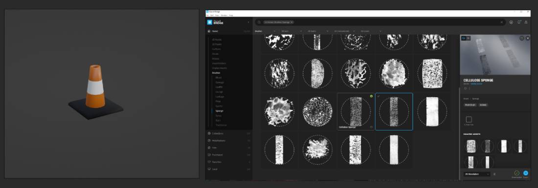
3.6.3
3.7 AR Scenes
As part of the individual project I created the following interactive Artificial Reality scenes where models of the Group Project Exercise were displayed. The scene was made using Unity 2019 with Vuforia engine. My main goal was to create and exhibit my models in an interactive setup at the Transmedia 2022 student exhibition.
Utilizing the Vuforia engine an development tool to build AR experiences that interacts with objects and the sorrounding environment in a realistic fashion. Beneficially Vuforia supports both PC, and mobile platforms.
3.7.1
3.7.2
3.8 Time Management
Time management is a skill I am still improving. I made preparations before the semester to devise an efficient plan for this semester knowing that I voluntarily took up more projects that it was required. Preplanned my daily tasks weeks in advance helped to stay on top of things. Unfortunately I could not anticipate a serious encounter with Covid-19. As the interruption have rendered me unable to work and study for three weeks I was forced to trying to catch up with weekly tasks at the university for the rest of the semester further delaying my assignment works. When I returned a typical week consisted of often 10-14h hours of work beside my weekend job. (3.8.1) From this perspective I can confidently say my time management was rather good but such an extensive off period could not be factored into the project planning. As a consolation for future projects I shall keep a similar strategy. Preplanning my steps in advance and without an unfortuous long brake I will surely complete all my tasks well before the deadlines. I prepared a group gantt chart that I shared with my teammates to fill. The chart shows each individual person's work phases. (3.8.2)
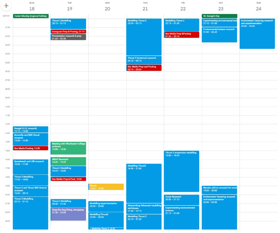
3.8.1
3.8.2
3.9 Conclusion
I very much enjoyed working on this project. Should the three week off period never happened I would have a completed VR scene I can be proud of. My plan for upcoming days to finish texturing the car and hand the model over to the client. As for the VR environment I would like to complete it during the summer months. I learned a tremendeous amount of skills most of which considered advanced level techniques throughout this assignment. Although it was considered a group assignment we all worked on our own nevertheless the experience of being a team leader still helped to gain some valuable managerial skills. Despite the unfinished scene I am still proud of the outcome of the model and looking forward finishing the scene. (3.9.1 - 3.9.3)
3.9.1
3.9.2
3.9.3
References
Hudson, T. (2022). The Ackroyd Collection - Gallery Five. [online] Woottonbridgeiow.org.uk. Available at: http://woottonbridgeiow.org.uk/ackroyd/gallery5.php [Accessed 23 May 2022].
eBay. (2020). THRUST 2 (Thrust2) World Land Speed Record (WLSR) Car Stamp (2009 Guinea-Bissau) | eBay. [online] Available at: https://www.ebay.co.uk/itm/THRUST-2-Thrust2-World-Land-Speed-Record-WLSR-Car-Stamp-2009-Guinea-Bissau-/401673666129 [Accessed 23 May 2022].
eBay. (2021). THRUST 2 (Thrust2) World Land Speed Record (WLSR) Car Stamp (1997 Gambia) | eBay. [online] Available at: https://www.ebay.co.uk/itm/402033390475 [Accessed 23 May 2022].
Bloodhound Education. (2019). The Land Speed Record | Bloodhound Education. [online] Available at: https://bloodhoundeducation.com/fast-facts/the-land-speed-record/ [Accessed 23 May 2022].
Performance Racing Industry. (2020). Bonneville Speed Week On Track For 2020 Race. [online] Available at: https://www.performanceracing.com/magazine/industry-news/07-29-2020/bonneville-speed-week-track-2020-race [Accessed 23 May 2022].